tl;dr: At 80 kHz where the MOSFET switches 0.5A at 5V, a gate driver makes a small but measurable difference in switching speed. It makes a clear difference in heat generated as you switch increasing amounts of power.
It’s better to do PWM at a high frequency. Ideally, you want the frequency to be well above the human flicker threshold, say at least a few hundred Hz, and then also above the human auditory threshold, say 20 kHz, because it turns out that some parts can go microphonic and create a hum. In fact, it’s probably good to be well above that, because of overtones and harmonics.
I decided I wanted to at least take an empirical look at switching more than minor amounts of power. See, MOSFETs are relatively complex devices to work out all of the figures but you can actually ignore a giant swath of parameters by using a pull-down resistor for safety and then adding resistor in front of the gate, so as to prevent it from blowing out the pin on the controller. The standard advice is that if it’s about 100Ω, it’ll probably work well up to some tens or hundreds of kilohertz as long as you use a logic-level MOSFET.
I don’t have an oscilloscope, so I’m using my logic analyzer as a proxy for one and keeping the voltages right around logic level.
This caused me to kinda went in some odd directions because I don’t entirely know what I’m doing. See, I had picked up a phototransistor (a BPW77NA) that’s designed to react quickly, because it seems useful to be able to measure the actual final PWM rate from devices, but that didn’t work out because it was still ending up with lag times approaching microseconds, not nanoseconds.
I also connected up some protected MOSFETs and found that the data sheets are completely truthful in that a lot of them have response times that’s not nanoseconds but microseconds and that’s not something that a gate driver will do anything about.
I also discovered that the results from a 400 Hz PWM train weren’t indicative of what it was like to throw a higher-frequency signal at it.
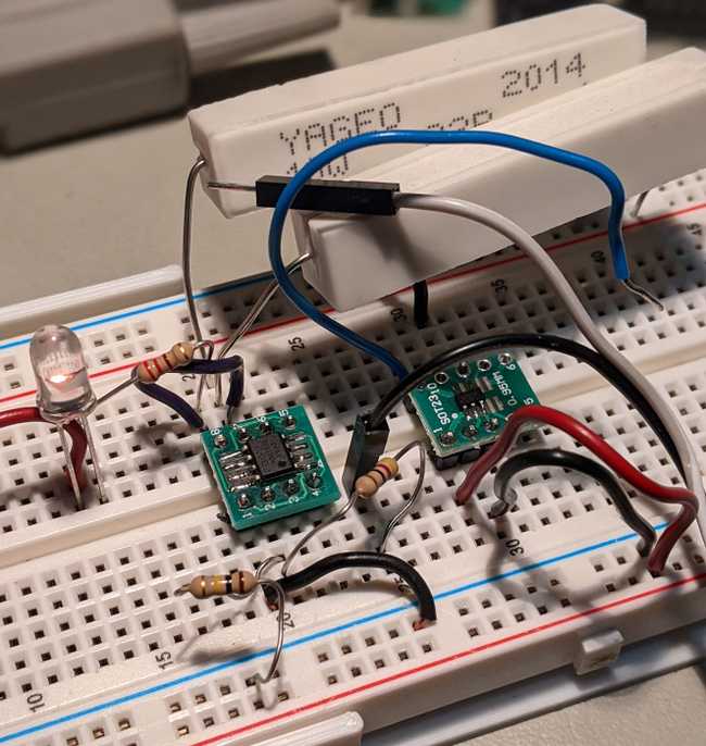
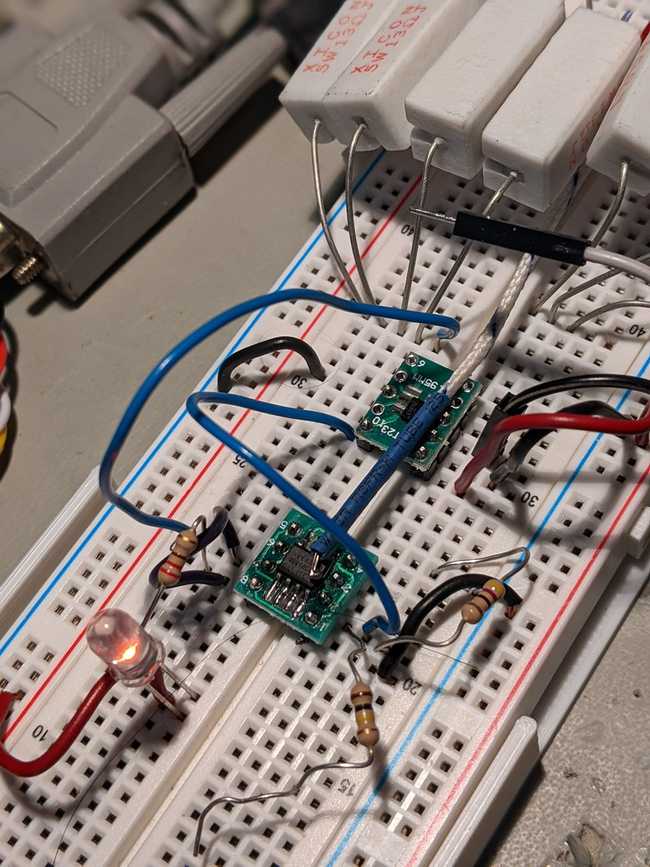
My final test setup looked something like this:
The version above the line is the more-or-less standard setup for a low-side switch, where R2 is my fake load that’s a big beefy 22Ω / 10W resistor to burn up some power, maybe 0.25 A or so. For my later tests, I put a pair of them in parallel to burn up more like a half-watt.
The version below the line uses a FL3100 gate driver, which is a fairly simple one that doesn’t have a charge pump to raise the gate voltage or anything. The FL3100 already includes a pull-down resistor, so I left the resistors out. And for the MOSFET, I’m using a DMN3018SSD, which is not advertised as a logic-level MOSFET but the VGS(th) is right about at logic level anyway, and then I was comparing between TP1/TP2 and TP3/TP4.
I was driving it with one of my arduino-esque boards and the FastPwmPin library, which is able to get an ATMega328 board up to 4 MHz.
At 80 kHz, I was able to measure some actual gate delay as well as seeing how the gate driver sped things up, because the conventional approach had around 200 ns of gate delay, whereas the FL3100T managed to get it down to 80 ns, which is about as fast as I can measure.
It would be nice to run this on an oscilloscope (which is a point of constant annoyance, because I don’t have room for a proper scope in my geekroom and none of the USB ones that connect to your computer have reviews that make me especially comfortable with blowing money on one).
Presumably the effect of using a gate driver increases as you go. I’m still not using absurdly massive MOSFETs with giant gate capacitances, they are still a little bit modestly sized, really. A gate driver can be driven by higher voltages than logic or it can be the type that comes with a built-in charge pump.
But I’m kind of at the limit of measurement with what I’ve got, sadly, because it can still be meandering between voltages or ringing or whatnot.
I did find one thing I can measure: Heat.
In theory. A MOSFET that takes a long time to ease it’s way between off and on states is going to burn up a considerable amount of energy and thus create heat.
I switched out the resistors and software until I had something like .75 amps of power being PWM’ed at 800 kHz, with a parallel set of 13Ω resistors and then I put a thermal sensor atop the part. Without the gate driver, it stabilized at 114°F. I then switched over to using the gate driver and the temperature promptly fell to 95°F.
Thus, I can conclude that you can get away without using a gate driver into the tens-of-kHz range with a modest amount of current. However, adding a gate driver makes the MOSFET switch faster by a measurable amount and that means that it will give you a measurable reduction in waste heat generated. Even if you are using a really quite inexpensive part like the FL3100, which is less than a dollar per part.

