Some five months ago, I wrote about how I got started with ESPHome with an ESP8266 and a temperature/humidity sensor on a breadboard.
I figured that I’d build it over time. I’d realize that there would be something that would be really nice to add, and so I’d find some parts to do it, or try out circuitry intended for other projects on it.
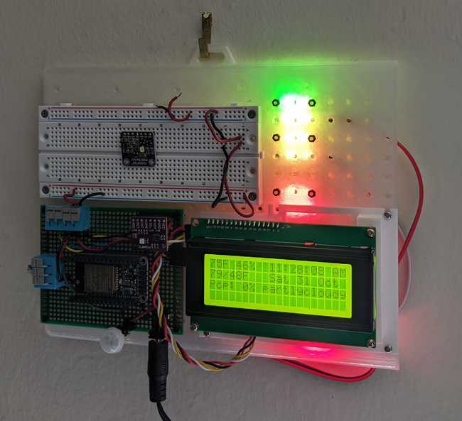
That particular setup has been sitting on my desk until today, gaining and loosing bits as I go to try and figure out what the right configuration ought to be, but today I finally decided that I should at least make the attempt of leaving it nailed to the wall for a bit.
RGB or RGBW LEDs
Every so often, I get obsessive on a project in my geekroom and screw up my sleep cycle. Now, I know that on the scale of disordered sleep, my level of insomnia is far beneath where some folks I know are, but I’ve been kinda obsessing over providing myself better mechanisms for knowing that it’s time to go to bed.
One thing I kinda wanted was some sort of intelligent light. Ideally, it’ll be a little bit like a second sunset for me, starting out relatively bright after sunset with some white components, and then becoming more pure red and dim as it’s time to go to bed. So this gives me two cues. First, the brightness cue in the room, but second that I can actually look at the LED out of the corner of my eye to know that it’s getting late.
My usual standard LED for interesting effects is the APA102. It’s much more tolerant of timing than the one-wire LEDs and generally is able to update faster and also generally PWM’s faster.
However, an array of red, green, and blue LEDs are not good for actual white light. And it would be nice to use it as such, so I decided that this setup would use NeoPixels.
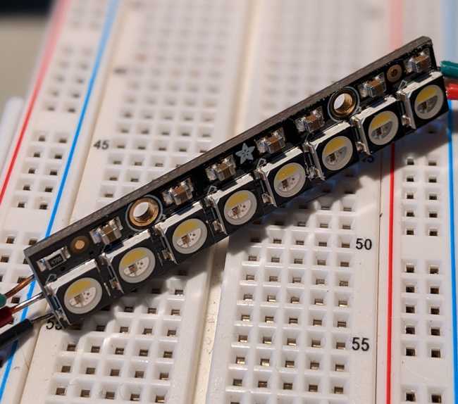
I got myself an Adafruit RGBW NeoPixel stick of 8 LEDs and wired it up.
I guess my big observation there is that the white channel of an RGBW NeoPixel is way way way more powerful than the mixed-white you get from the RGB LEDs. So it feels like a better choice for devices that are at least partially light fixtures.
LED Automation
I spent a bit of time messing around with this until I figured out the right way to do the lighting.
My first attempt at automation was to just set something up in Home Assistant. But Home Assistant is not really set up to command a light quickly or frequently.
It turns out that the closest to right method was to create an Effect that runs inside of ESPHome and then it can use the sun position and time to figure out the right level of lighting to use, and then use an automation on the HA side to ensure that the right effect was triggered at sundown.
LCD Display
I didn’t really feel like implementing my own display driver for ESPHome or spending bunches of time playing with people’s not-yet-merged beta stuff, which means that, when I was buying displays, there were fairly slim pickings, mostly OLED displays, character LCDs, or ePaper displays.
OLED displays are out because they dim too fast for something that I’d like to have always visible.
ePaper displays are neat, but they are also a bit spendy for the size.
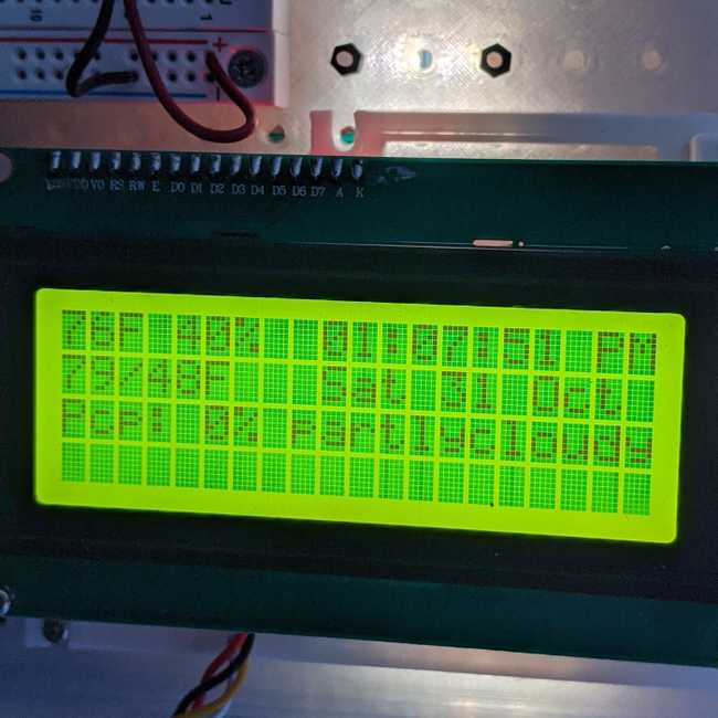
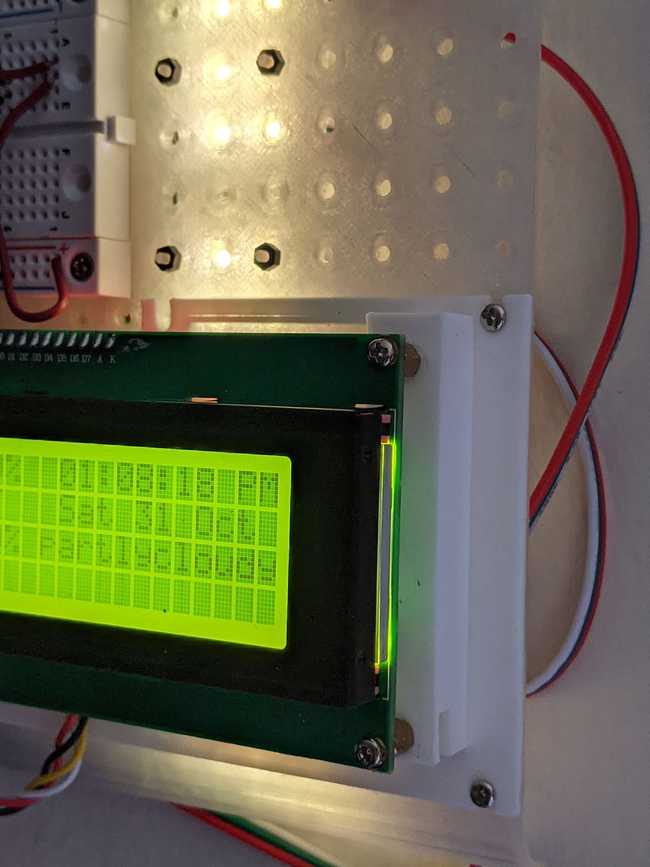
But regular character LCD displays would work fine and are easy to find. I only really needed a 16x2 LCD but I went for a 20x4 LCD because why not?
ESP8266 to ESP32
There weren’t really any convenient pins on the ESP8266 to drive LEDs with. See, the ESP8266 has a few ways that it can drive the NeoPixel protocol but once I looked through my options, the only one that worked out well was bit banging.
This meant that the timing was off just often enough to cause the LED to strobe green.
This is why the APA102 design is better in a lot of ways, except that nobody makes RGBW LEDs with that protocol and it’s an extra wire to solder up which can boost your complexity with a long strand of lit-up-bits.
Between having more ways to drive NeoPixels as well as having a second CPU core, I decided that maybe I should just use the ESP8266 board (that I’d got for unrelated reasons that didn’t pan out and was re-purposed into my ESPHome setup) for something else and switch to an ESP32. Which largely solved my problems with driving NeoPixels.
Chassis ideation and the 5mm × 5mm grid
The thing that’s been bugging me about some of my projects is that I can kinda know where a good stopping point is, but I also can’t guarantee that’s where things will end. I don’t have room to necessarily store cast-off bits either.
I also figure that this is the setup for my geekroom. This isn’t a fancy thing that needs to be a finished chassis.
So, I figure that I wanted to at least have a display, the mainboard, and some LEDs.
The mainboard is easy. The largest circuit board I’ve got in my assortment of cheap questionable PCBs is a 7cm × 9cm, so I might as well use that.
I figured that one way to enable changing things over time was to throw in a breadboard. Well, it turns out that Global Specialties makes breadboards with convenient screw holes for mounting, because I’m not trusting the adhesive on the back of breadboards.
Now, the display right now is an LCD, but I’d love to have the option to put something else on. Maybe one of those 320×240 displays with an ILI9341 driver that’ll eventually end up in the ESPHome support list so I can give it an LCARS style interface or something.
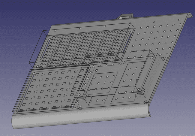
I figure the best way to do things is to make a pegboard out of it. And because FreeCAD is very obviously written by people who live in a Metric world, I decided that a 5mm × 5mm array of 3mm-ish holes seems reasonable. This way, I can use M2 or M2.5 spacers and screws to mount stuff.
One thing I learned from real engineers is that your designs go better if you take the immovable blocks of the design and then figure out how to package that into a final design. So I started just by making boxes of the general size of the parts.
Then, I designed a base board that’s about at the limits of what can sit into the array of random other people’s Prusa i3’s that TreatStock is armed with in terms of two of the dimensions and it’s got permanent holes for the breadboard and mainboard, and then the rest of the area is an array of pegboard mounting holes. And then I just made sure that I had an appropriate mounting bracket for the LCD, which required a bit of care because it almost didn’t fit.
After some conversations on the Adafruit Discord, I decide that the funnest way to do things is to make it fabbed from transparent material so I can mount the LEDs underneath to diffuse them some. Which is, quite honestly, an amazing effect.
RGBW 4-banger
One thing I do is assemble a bunch of random ideas and circuitry bits into a single larger PCB, where everything has little mouse bite breakoff tabs, and send it off to DirtyPCBs to be fabbed.
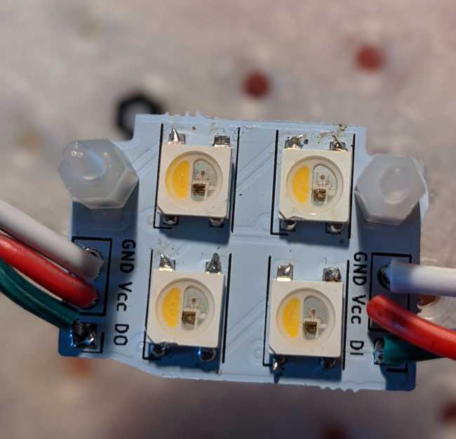
In my most recent batch, once I realized that RGBW NeoPixels were kinda neat, I decided that I might as well make some of my own PCBS to hold them.
I decided that about the right size for me was a little 2 × 2 grid of LEDS with mounting holes that fit the 5mm × 5mm pegboard spacing the board would have. This also has the positive attribute of not having me assemble something that’s already on the marketplace out of fastidiousness.
Headers, terminal blocks, and connectors
There’s a very long and comprehensive article on exactly why trying to crimp your own DuPont connectors is hell that I won’t repeat.
Dupont connectors on a 0.1” grid ought to be great. They are totally great for board-to-board connectors. But if I want to make my own connectors, they are just annoying because you literally cannot get a crimper that will crimp them well enough.
Also, the general not-really-standard-at-all standard for NeoPixels is to put them on a JST-SM connector, where at least some of them match the SparkFun writeup so I standardized on my strips using that as their pin out.
I decided that I was only going to use a header on the connectors that were either going straight from one module to another with a cable that someone else crimped or were board-to-board connector. So the temperature/humidity/pressure sensor board got a header, the motion sensor got a header, and the LCD got a header.
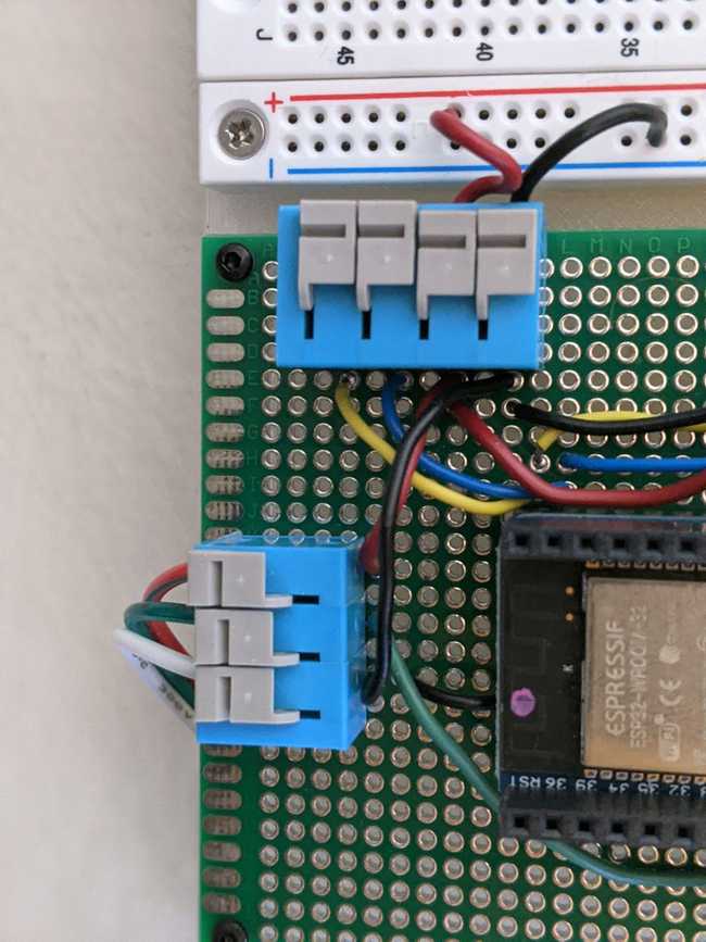
I put a few different connector types for trial in my cart. The default option is some 0.1” and 0.2” screw terminals.
However, as someone who has the distinct impression that someone probably has a canned product that’s meant to solve exactly and precisely every single connection need you have but you need to find it, I did some research for alternative. And a few products from CUI devices caught my eye.
There’s the TBL009-254 and TBL009V-254 series of 0.1” screwless push-button terminals and then there’s the TBL004-508 and TBL004V-508 series of 0.2” screwless push-button terminals.
Now, the downside is that they are a bit bigger than the screw terminals, but otherwise they are inexpensive connectors that will fit into a standard perfboard just fine.
Final-ish sensor layout
Right now, it’s got a humidity-pressure-temperature sensor and a motion sensor as the primary sensors.
The motion sensor is connected up but not automating anything yet, which is an upcoming project.
Power supply
I spent some time debating with myself how to power it. See, for most of the time, it was powered by a USB breakout. I had some notions of maybe using one of the 12V LED silicone neon-ish LED modules on it, so having a 12V option might have been nice, but eventually I just went with a “tabletop” 5V interface brick because I can string that cable a little bit of distance and the extra power mostly serves to give me headroom to connect other bits down the road to the board.
Putting it all together
I think the main mistake I made was not measuring the LCD module and the existing Adafruit LED quite thoroughly enough. The LCD module is a bit jangly and the Adafruit bar of 8 RGBW LEDs doesn’t fit in the screwholes. Then again, I can use it for something else since I’ve got my nice 4 LED modules.
But it’s done-ish for now. I mean, you can see that I’ve already got some stuff on the breadboard to mess with. And, if nothing else, it could maybe benefit from a few more LEDs. And I still want to work a bit more on some of the software parts of things.
