This update covers many months of using the printer, working on things, etc. Including a giant burst of printing to get everything together for the Maker Faire and also some periods where the printer sat idle and not-quite-functional because I had to go to funerals and things.
General improvements
- Instead of using one of the fancy tools, I just used the builtin
SHAPER_CALIBRATE. I’ll probably obsess over it more when I’ve got it closer to the final configuration. But it’s kinda obvious that the Tap makes things jiggly. My old Ender was accelerating at 500 mm/s2 and I’ve got it accelerating at 4000 mm/s2. 4k accels is enough to give it that freaky fast-printing feeling. - With a 0.4mm nozzle and PETG, I’m mostly limited by the 60mm/s speed limit for PETG and/or layer time. If I switch to a 0.6mm nozzle and PETG, I’m volumetric flow rate limited. I have some CHT nozzles and I haven’t seen how much I can squirt down those yet.
- I used the slip in brackets to make it easier to insert the deck plate. I ended up removing the provided supports in the back because they were just getting in the way. I ended up needing to jiggle things a bit to get it all to slide in perfectly. But I do have the deck plate closed, which is good because one problem with the inverted electronics is that you can drop a bolt into the works and zap stuff.
- I put a Waveshare CM4 heatsink on and that definitely helped the Pi’s temperatures.
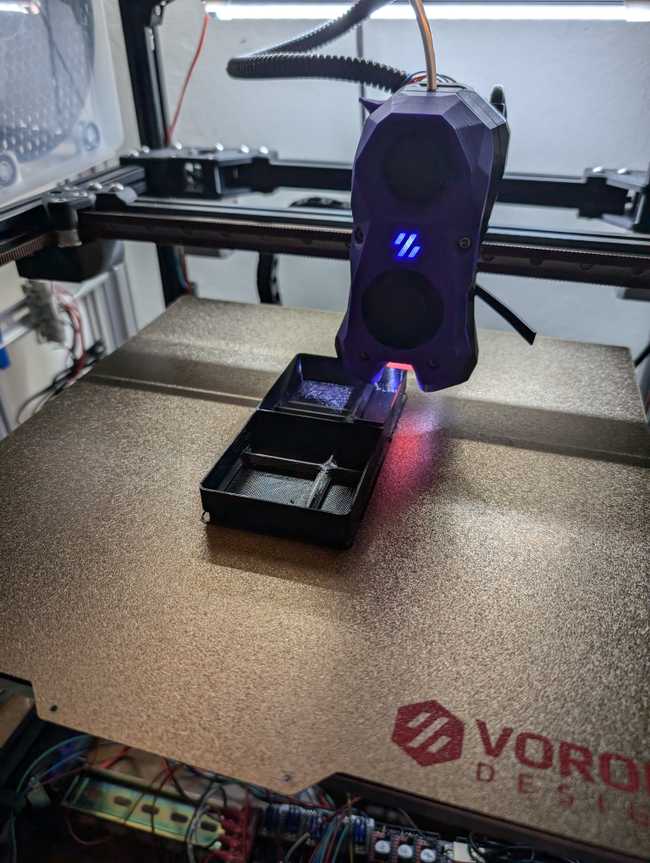
- I re-printed the Y Endstop relocation mod in Plutonic Purple ABS now that I’ve got that spool open.
- I’m going to use, at least for starters, the Voron 2.2/Annex panel clips on the side and top panels.
Tap to Beacon
Ryan: “I have a 9 point mesh. How many points does your ABL have?” “Yes.”
After finding out that allegedly the Tap sensor is going to limit my speeds and finding out about Beacon adding a contact mode, I’d planned all along to get a Beacon.
I figured that the right way to do this is to get the Beacon probe going first, then switch over to a new toolhead as a second step.
So I started yoinking the tap. I printed the non-official Annex Beacon carriage. I tried some of the magical solutions for redoing the belt without having to re-tension the whole works. One of them was awkward. The other one cracked, although I’d screwed up printing it so I’ll try that one again. Finally I just gave up on being fancy took advantage of having fairly good relative pitch to re-tension the works because after all it doesn’t take me that long.
I’m not sure exactly what’s wrong, but the X-limit switch for the Annex mount is something like ~1-2mm too far. I was just checking, powered-down, and it was kinda obvious. I ended up taping a piece of filament on the XY joint to make it a bit thicker. Kinda confused as to what’s going on there…
The sensor looks to be 0,28 from the nozzle.
I also had to fight with the prind docker image and the Beacon installer. It turned out that the best way to get it going was to replicate the installer shell script as a child docker container.
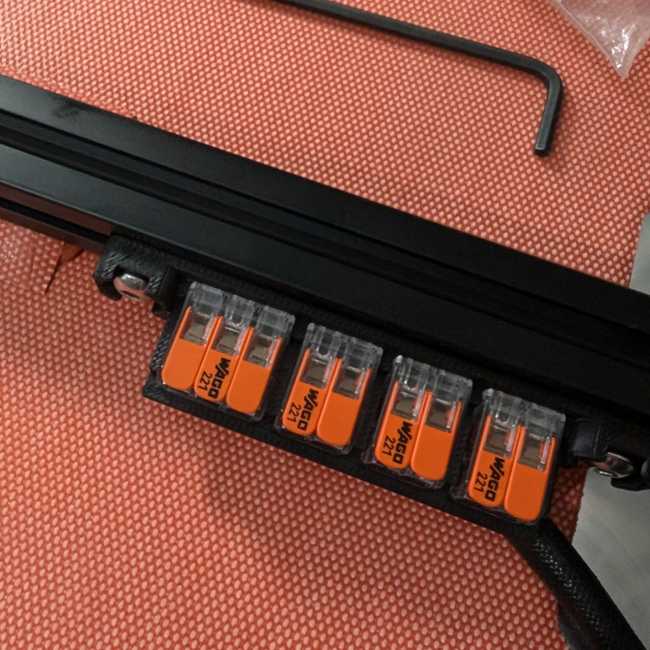
I also had to print a DIN rail bracket for the Waveshare USB-HUB-4U hub that I got because apparently the USB on the Manta is slightly iffy according to the Beacon folks.
Overall, it feels like an improvement. For several reasons:
First, while I still haven’t actually sat down and plotted the graphs from the data and used that to hunt down screws to tighten, the difference in what SHAPER_CALIBRATE suggests is dramatic. So, clearly, the tap sensor jiggling really is hurting the performance, that’s not just random allegations. I went from 4k accels to a conservative 8k accels.
Also, and this is probably a bit my fault for being potentially a bit lackadasical in my Tap construction, but the overall accuracy is a lot higher. But I guess this still counts as an advantage - the Tap is a very neat design with some careful compromises and design thinking but you have to assemble it. The Beacon (or Cartographer or other such sensor) is a largely solid-state device that is fabbed and all you need to do is screw it on. So I upped the required tolerances of bed leveling because it tends to be right on the nose.
Finally, the Contact workflow is better than I’d thought. With Tap, you need to keep the nozzle de-schmutzed before every print, understanding that’s actually really hard with PETG because it really wants to booger out the nozzle. Contact can still work in a mode where it does a touch sensor every print. However, there’s also a BEACON_AUTO_CALIBRATE command that I can run which will calibrate the probe with the touch mode and then save that model. So instead of having to do the touch sensor every print, I can use the touch sensor only when I change the bed or the nozzle.
I don’t need to figure out the overall offset for tap the way I did with tap, but I did discover that I need to adjust the z offset up 0.1-0.15 if I’m using a wider nozzle.
Thus, I definitely don’t want to use the brass nozzle brush because it might short the self-test contacts on the bottom of the Beacon and also scrape the coating off of my coated nozzles. I decided against the Bambu nozzle silicone thingies because they seem to be quite short lived. I’ve got some high temperature silicone that’s suitable for making a nozzle brush out of and I guess I still want to mount it, but it’s a lot less important versus just manually scrubbing the nozzles still. So that’s still an open question.
Either way, I have some Slice Engineering Vandium nozzles and they are 0.1mm or so off from the “standard” and so I’d always have to mess around with the Ender 3v2 whereas I can just tell Beacon to auto-calibrate and everything’s fine.
New toolhead, first try
A conversation a while ago on the Voron discord indicated that the VZ-Hextrudort Low with the non-twisty gears was the best TPU-focused extruder. And then I also decided that I wanted to have relatively simple wiring for the toolhead, so I got the Mellow-Fly SHT36 V2.0 toolboard because the NH36 seems like a bit of a disaster.
I was thinking about either the Xol or the Dragon Burner. The big thing is that the Dragon Burner fits on my Zero whereas a Xol will not, so this way I’ve got identical toolheads. Also, the Dragon Burner has a slot for a thermistor that sits against the heatsink.
I decided to get some fancy Delta fans. Xol recommends the BFB0405HHA-A 4010 blower and the ASB02505SHA-AY6B 2510 axial fan. I got the same blower but ended up getting the ASB0305HA-DF00 fan that seemed to be fairly close.
- The cable that came with the SHT36 is too short for my printer but thankfully I’m able to re-use the cable that came with the printer.
- The packaging for Katapult assumes that it’s running alongside Klipper. I spent some more time and decided to see if I really really needed to use it or if I can just use the standard Klipper interfaces for things.
- After I’d gotten into it, I realized that the SHT36 V2 toolhead only supports a PT100 sensor, not a PT1000. I want the SHT36 V3 with the PT1000 instead, so I’ll get back to working on this later.
Chassis grounding
This came up on the Voron discord one evening after work.
I’m not really sure if this is worth obsessing over. I have never seen someone ask “Hey, I get a spark when I touch my Voron, what’s up?” and generally the times that 3D printers in general have done something dangerous, it’s been that they caught on fire.
On the other hand, there’s been a lot of complaints about glitchy toolboard designs. LDO had to recall the NH36 boards. Triangle Labs ships theirs with a bodge wire to connect the stepper chassis to the neutral wire.
In an ideal world of properly made electronics, all of the pieces of the chassis are bonded and connected to safety “earth” ground, which goes to the safety “earth” ground lug in your electronics plug, which is connected to the actual earth via a code-compliant mechanism, generally a grounding post and potentially a bonding strap to the neutral lug coming in.
It’s important to note that while the electrical potential between the neutral ground and the safety “earth” ground should be zero, they are not the same. The neutral ground has the return current flowing to complete the circuit. The safety “earth” ground is there to dissipate spurious currents like ESD or noise. If you look at the block diagram for your PSU there’s an isolation transformer that is required by most electrical codes.
The construction guide specifically has you connect the safety “earth” ground to the frame and the build plate via ring terminals. I added a toothed locknut to the frame’s ground connection to make sure that it scratched away any powdercoating.
Most Vorons are anodized or coated with a presumably not conductive material to make them have a stylish color. At least for my Formbot frame, this happens after the frame has been cut and tapped. This is a problem because it means that when you bolt a frame together, it may not be grounded properly.
Several of us did a quick test. If I probe two points on the coating, I do not get connectivity. However, if I probe the left and right side linear rails, I do see connectivity. So, in spite of everything being powder coated, there’s apparently at least some grounding happening?
Now, allegedly there’s a bit of a problem with static electricity building up as filament moves through the bowden tube which may be responsible for signal glitchies and fried boards. From what I understand the conductive chassis of the stepper motor is meant to go the protective earth (green/yellow striped), not the neutral ground. This mostly makes sense — you don’t want any static electricity spikes on the V- line. That’ll glitch your toolboard.
It would also make sense to spray some conductive spray on parts of the toolboard and maybe have it enclosed, to further prevent EMI glitchies.
Either way, I’ve got some ring terminals on the way so I think I’m just going to add an earthing wire to the stepper motor’s body.
Broken endstop, PUG umbilical, and then minor tweaks to the StealthBurner
The metal thing on the endstop broke, so I found a suitable spare switch but I screwed that up while heat-shrinking the tubing onto the leads, so then I switched to the Creality Limit Switch version of the endstop. And then after I’d gotten that working, the metal thing broke again.
It might have been getting hooked on some of the wires?
I wasn’t entirely a fan of the supplied corrugated tubing nor the glands, so I decided to use the PUG system. After measuring the size of the combination USB+CAN cable, I realized that the 3/8” Slit Corrugated Sleeving that I had gotten for my Ender’s umbilical was about the right size. I used the CW2 mounting umbilical arm on one side and the A drive mount on the other. The endstop relocate conflicts with the PUG mount, so I just bodged with a long screw.
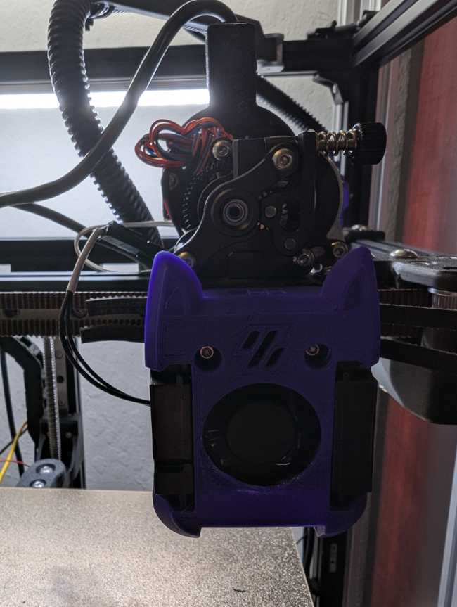
Also, since I really wanted to print some PET-GT and HTPET+ and the StealthBurner’s a bit marginal, I decided to just upgrade the fan to a Vindr from West3D so that I’d at least have a pretty potent fan to cool the hotend and that wouldn’t represent me spending a lot of money on a toolhead I am just going to replace shortly.
There’s not enough room for JST-XH connectors in the StealthBurner’s face so I had to use a Molex connector. And for whatever reason, Molex connectors are always a giant pain in the butt, although I will probably get a different crimper tool and try again at some point. But, with the tool and connectors I’ve got, I managed to get at a passable crimp on the fan’s wires. It’s a 3 wire fan so I ended up making a 2 pin connector that goes to the normal fan port with the black and red wires and then put the yellow tach wire into the 4 pin port so I could just use the sensor.
Assuming the tach doesn’t lie, the Vindr fan is 9300-9600 RPM, which is close enough to the advertized 10k RPM, is at least annoying louder than the prior fan, and seems to be OK with me printing PET-GF so I’m guessing it’s a reasonable improvement over whatever the fan was that I got in the Formbot kit.
Anyway, I lowkey hate sensorless homing, but I switched things over. I’m kinda frustrated because I would have maybe had a working printer earlier if I’d just switched earlier. I want to switch back, mostly because I want the better accuracy from the switch so I can eventually do things like frame temperature compensation and speed tests using the endstop as reference. The annoying part is that you need to follow the special Beacon override section while also following the Voron guide.
The main area I got tripped up is that it’s really hard to get the jumpers for the DIAG pins inserted properly.
Note: The DIAG pins on the Manta are 2.0mm pins, not 2.54mm pins, which I discovered later when they got flakey.
A print farm

After some frustrations with the endstop and everything, I got both the Zero and the Trident printing at the same time so I could wrap up a printing project. While both printers are noticeably faster than my Ender 3v2, the real dramatic improvement in print speeds is if I can get them both going at the same time.
New toolhead, second try
I dono, the StealthBurner feels like it’s a lot of overly fancy design and poor ergonomics.
Which I guess I can’t quite critique because … part of why the Voron is a thing is design and aesthetics.
But there’s little things like.. if I’m supposed to adjust the gear meshing, why is the gear in the most awkward position possible to determine if it’s meshing right?
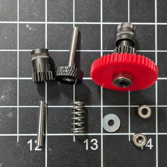
Anyway, the most annoying failure I’ve had so far is that the idler gear popped out of the tensioning arm, which was an annoying failure mode because things would kinda work, but not right. This required a lot of monkeying around. Eventually the heatbreak got clogged with HTPET+. Ugh. Thankfully, it happened after the SHT36 V3 arrived.
Some folks on the Voron discord were talking up the Dragon Ace as a standard-height higher-flow well-behaved printhead, so I had picked up one.
Thus, the configuration is a DragonBurner with a Mellow SHT36 V3 controller board, a Dragon Ace hot-end without the MZE, and the VZ-Hextrudort Low extruder, where I’ve got a tach on the hotend cooling fan to detect a fan failure, plus a thermistor against the heatsink to detect an impending heatbreak clog (or provide a second way to detect a hotend fan failure).
- Still not bothering to use Katapult.
- In order to use two thermistors without running extra wires, I have a PT1000 running into the MAX31865 which frees the regular thermistor port up to run the heatsink thermistor.
- I had seen some people post variations on the DragonBurner mount for the extruder but the standard one was fine?
- I ended up using 2 x M3x16mm to secure the extruder mount to the hotend mount and it looks like the PTFE tube needs to protrude from the hotend mount 13mm.
- To run two fans off of one connector, I ended up checking out NASA’s workmanship standard and decided that if NASA considered it OK to do an inline branch using a solder sleeve for a space shuttle, I’ll use it for my 3D printer.
- The Dragon Ace comes with Molex Micro-Fit 3.0 connectors for the power and the PT1000. I made up a little jumper bit for the screw terminals and ended up snipping the PT1000’s Molex off and directly replacing it with a JST-SH, which was a bit of a leap of faith but it turns out that the wires were 26 gauge and therefore would crimp.
- It’s really annoying to crimp JST-SH connectors by hand. I can do it, but it’s annoying.
- Also, JST-SH connectors need to be 24 gauge or smaller wire, which meant I had to source some extra wires.
- I’m keeping the “endstop” pins empty and running the tach for the fan into the “Probe Servo” connector where the Z stop would be.
- I ended up needing to change the config to use a pull-up because the Delta fan has an open-collector output (Most of the time you want to use the
^ to engage a pullup) as well as set the tachometer_poll_interval to 0.0011 because the default wasn’t fast enough for a 10500 RPM fan. - There is no PCB holder that has the PUG umbilical. I was poking around designing one but the version I’ve got doesn’t quite work and it holds the umbilical too high. I might just go back to zipties.
- I have never been able to make any of the quick and easy solutions for holding the belt in place while I swap things work. Ugh. At least I’ve got a musical ear from tuning guitars.
The “Alternative Voron Mounts” section is a bit under-documented.
- I printed the MGN12H mount with the PCB mount holes, which means that the PCB isn’t mounting to the two spacers but to the lugs on top. You want to insert two square nuts into the slots on the side, that’s where the DIN557 size is right, not the thinner kind. And then there’s a pair of heat-sets that go into the lugs and a pair of heat-sets that go into the bottom where the carriage base connects. Except that one of the heat-sets came loose.
- I printed the carriage base short version with the X-stop switch mount. That seems to use a M3x8mm screw?
- I also printed the probe mount for the Beacon which needs a pair of heat-set inserts for the Beacon side and a pair of heat-set inserts that go in the back.
- There’s also two heat-sets that need to be added to the cowl (I printed the cat cowl because of course) to reinforce the whole works from the bottom.
- The design calls for a M3x12mm screw to secure the toolhead to the carriage.
- I slammed the Beacon mount all of the way up. It probably doesn’t matter too much but I figure this is less likely to end up wrong?
- I’d somehow assumed that the temperature sensor against the heatsink was meant to be a cartridge styled sensor, but the one I put in there had a broken wire right away and another cartridge sensor just straight up failed to fit, so I guess I’ll put a bead sensor in instead.
ASA-GF is … not great?
ASA tends to be less temperamental, albeit more expensive, than ABS.
I’d wanted to print a full Nevermore Micro for the Zero and it warped. So I decided for my next spool of black ASA filament to get some a spool of Siraya Tech FibreHeat ASA-GF to see if that would make my life easier?
As it turned out, it didn’t do any better of a job on the Nevermore Micro. Plus, some of the Voron parts I printed with it just didn’t work because while the fiber reinforcement is increasing the structural strength in the XY plane, it hurts the strength in the Z axis. Plus it feels “itchy” like all fiberglass things. Plus I kept getting filament breaks.
So, while my ABS-GF parts that Formbot printed my Zero with seem to be holding up, it looks GF doesn’t bring any real useful advantages?
Klippain Shake&Tune is great, albeit really annoying to set up in Docker.
After a few dismantlings of the gantry, I noticed that the accelerometer tests were looking super-sketch.
I’d avoided using Shake&Tune specifically because it requires effort to set up. On the other hand, it’s really handy.
What I want is to have declarative and repeatable releases such that I don’t get surprise broken by dependency updates and so that if the SD card gets corrupted on my Pi, I can wipe it and just run Ansible on the fresh node.
Shake&Tune is in a git repo that you clone and link into your Klipper install and it comes with some excellent documentation including images, but I couldn’t come up with a good way to git clone just what I needed without dealing with GitHub timeouts, but at least they ship releases.
So, here’s what my docker file looks like:
FROM mkuf/klipper:v0.12.0-286-g81de9a86

USER root
RUN apt-get update && apt-get install -y git python3-can libopenblas-dev libatlas-base-dev wget
RUN mkdir -p /opt/beacon_klipper && chown -R klipper:klipper /opt/beacon_klipper
RUN mkdir -p /opt/klippain_shaketune && chown -R klipper:klipper /opt/klippain_shaketune

# Install Beacon
USER klipper
RUN git clone https://github.com/beacon3d/beacon_klipper.git
WORKDIR /opt/beacon_klipper
RUN ls -al
RUN git checkout 730836d40f1bf02b6f1bf08649dcaacca9aee900
WORKDIR /opt/
RUN echo ${HOME}/klipper
RUN /opt/venv/bin/pip install -r /opt/beacon_klipper/requirements.txt
RUN ln -s "/opt/beacon_klipper/beacon.py" "/opt/klipper/klippy/extras/beacon.py"

# Install shaketune
WORKDIR /opt/klippain_shaketune
RUN wget https://github.com/Frix-x/klippain-shaketune/archive/refs/tags/v5.0.0.tar.gz
RUN tar -xvzf v5.0.0.tar.gz
RUN ls -al && mv /opt/klippain_shaketune/klippain-shaketune-5.0.0/* /opt/klippain_shaketune/
RUN /opt/venv/bin/pip install -r /opt/klippain_shaketune/requirements.txt
RUN ln -frsn /opt/klippain_shaketune/shaketune /opt/klipper/klippy/extras/shaketune
WORKDIR /opt/
Overall, I like prind, even though I’ve abused it to replace the Docker Compose with Ansible. I have a bias because I do infra for work. The problem is that kiauh works pretty well and it’s only real flaws are those inherent with running inside of mutable infrastructure so it’s a hard sell.
Now, imagine if there was integration with Klipper modules and macros against Mainsail and Fluidd and OctoPrint such that I don’t have to SSH copy my graphs over.
The PF Makes belt tension meter
In the process of building out the Voron, I’d stripped one of the screws on the Y gantry and that axis was a bit off, so I took the opportunity to get a fancy set of West3D’s Berserker MGN9H-1R-350 rails to replace the stock.
I also got the West3D fully assembled PF Makes belt tension meter. I’d been kinda fighting the stock status of it and finally it was in stock when I needed other things from West3D so that I’d get a pre-assembled one that was already configured properly.
I kinda wish I’d had one earlier because it takes a lot of the drama out of the belt tuning process, even though I have good enough ears to tune a guitar properly. I think I had the belts too tight when I built it the first time.
The Dragon Ace so far
I managed to clog the heatbreak, while changing filament. Not sure if this was user error, I probably retracted the filament while the hotend wasn’t hot enough and got it stuck towards the top.
Overall, the design of the Dragon Ace isn’t bad? You get a beefy stubby slot to remove the top part of the heatsink and then you can unbolt the heatbreak. It runs afowl of the Slice Engineering Mosquito patents apparently, or is at least close enough that you have to order it from TriangleLab directly instead of being able to get it on AliExpress. On the other hand, it’s way better than the Mosquito design which has you unscrewing a very long M1.4 screw that faces the build plate so it’s got a high probability of being gunked up.
Apparently the heatblock can be destroyed by tightening the nozzle too hard. And apparently the ceramic heater isn’t all that great. Either way, the specced power for the heater is too much for the V0’s power supply.
Either way, the fill rate is refreshingly high and much better matched for the overall speed of the Trident than a standard flow hot-end.
The SHTv3
Let’s review the options for toolboards, yet again:
- LDO makes the NH36, which sounded great but the first rev was a disaster and, overall, I haven’t been actually super-impressed with the LDO stuff I’ve procured so far.
- BTT makes the EBB36 which requires a bunch of messy wiring because it assumes 24v fans.
- Fystec released the H36 combo board that looks like it’s, in some ways, better than the NH36. On the other hand, there’s one bad review and they pulled the listing from aliexpress so I’m assuming that their first release is going … as well as LDO’s.
- Mellow makes the Fly SHT36.
- Luke’s Labs is beta testing the Jupiter toolboard that looks kinda close to overkill
- I could always not use a CAN or USB toolboard?
Toolheads are somewhat cursed, clearly, otherwise there would be a slate of entirely reasonable boards out there. I definitely feel like CAN bus is somewhat overkill for the printer’s electrical environment and USB is arguably a bit less temperamental. But the thing is, the board is going to get hot from a closed chamber, there’s a giant EMI interference generator right there, there’s a lot of power going through the board, and clearly there’s also static discharge from the filament rubbing against stuff.
Anyways, the Fly SHT36 V3 could be pretty good or at least good enough, however, mine has a broken screw terminal that likes to come loose, plus the LIS2DW seems to be broken, which I’d initially thought was because there was some resistors on the SPI lines before I’d realized that the LIS2DW and MAX31865 share a bus.
Other glichies
- Some of the Z axis screws came out. It looks like I should probably back out all of the M3 screws connecting to the linear rails and add thread-lock, although I might have more disassembly and re-assembly to go.
- I noticed that a chip came out of the edge of the A drive so I need to replace that.
- Bad cPIF part: Some of the hinges were printed wrong. It’s a print-in-place hinge and the two pieces were separated.
- I thought the idlers needed speedy replacement but the clicking was from the Z axis and they were bending because the tension was too high. I should still replace them.
- There’s no way to set the nozzle size at runtime for a Klipper printer, which means that I have to disable some of the safety features because I use a lot of different nozzle sizes.
Next up to work on
- Speed test, further tuning
- Mount the nozzle brush
- Figure out the nozzle purge situation. It’s less important to use pellet-style purge with a giant bed as compared to the Zero but I’m realizing that I really like not having purge stripes all over the place.
- Mount the panels. I printed out some of the Voron 2.2/Annex clips that I’m probably going to use for most of the panels I’d want to remove. The Coroplast sheets for the back seem to be more like 3.5mm instead of 3mm.
- One of the screws on the right side of the gantry is accidentally a M3 T-nut and so I need to dismantle that a bit to get an M5 T-nut in there. Ugh.
- Refactor the macros
- reacted for opsec reasons
- Nevermore air filter
- Mount the display. I think I’m going to just put in a simple display instead of the supplied fancy display.
- Bed fans
- LEDs for the Dragon Burner.
- also redacted for opsec reasons
- Chamber temperature sensor
- Filament sensor
- Serial number
- Replace the idlers and AB motor mounts, potentially try cleedlers, one of the geared cleedlers designs, or maybe the CNC idlers and motor mounts.
Conclusion
tl;dr:
- I’d feel worse about spending time doing printer mechanic things instead of useful printed things if it wasn’t for some recent Bambu asshattery.
- For the open-source / open-architecture side of the fence, we need to accept that some of the things that Bambu has done in terms of making printers friendlier should be copied over and included into the standard. The tension meter takes a lot out of the belt process. Shake&Tune is really great and things like it should be more tightly wound into the Klipper ecosystem.
- Beacon with contact is really really good. I’ve been procrastinating on getting some sort of nozzle cleaning solution setup because I only touch-probe when things have changed.
- Toolheads and hotend clogs are frustrating.
- A good belt tension meter ought to be part of any build.
- It would overall be nice to have a Large-Voron styled mount that comes in two pieces instead of an adapted Small-Voron styled mount for the DragonBurner.
- The Voron Trident at 300mm bed size invites the design of interesting large things and a Dragon standard flow is not enough, which is not a surprise really. I’m not sure if I’m going to exceed the capacity of the Dragon Ace for practical projects, although I need to see how much I can bump the speed up.
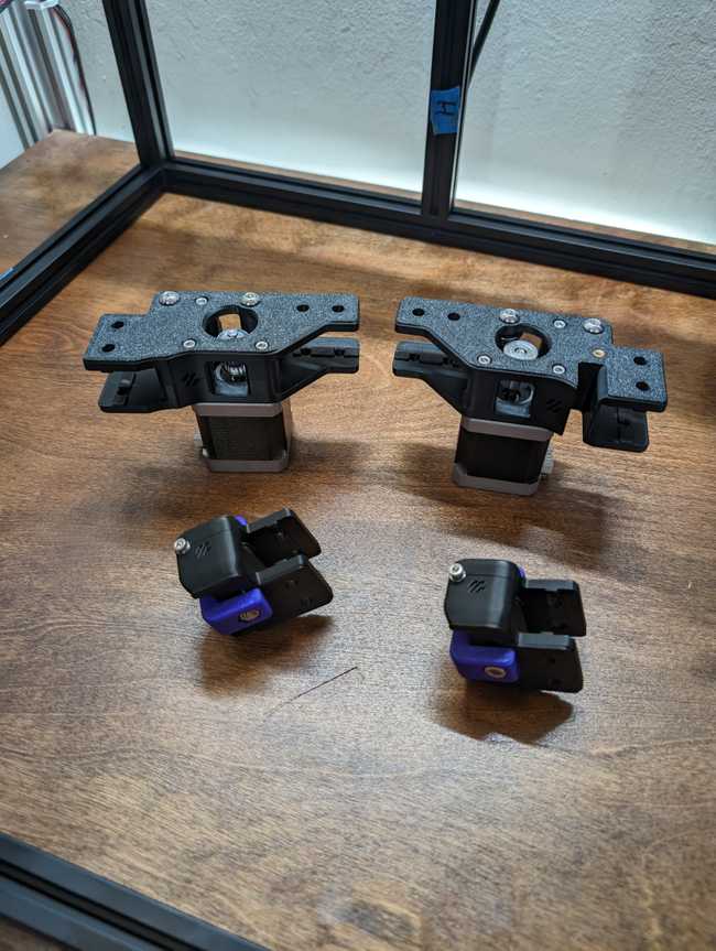
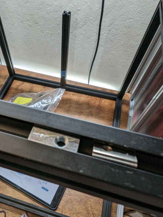
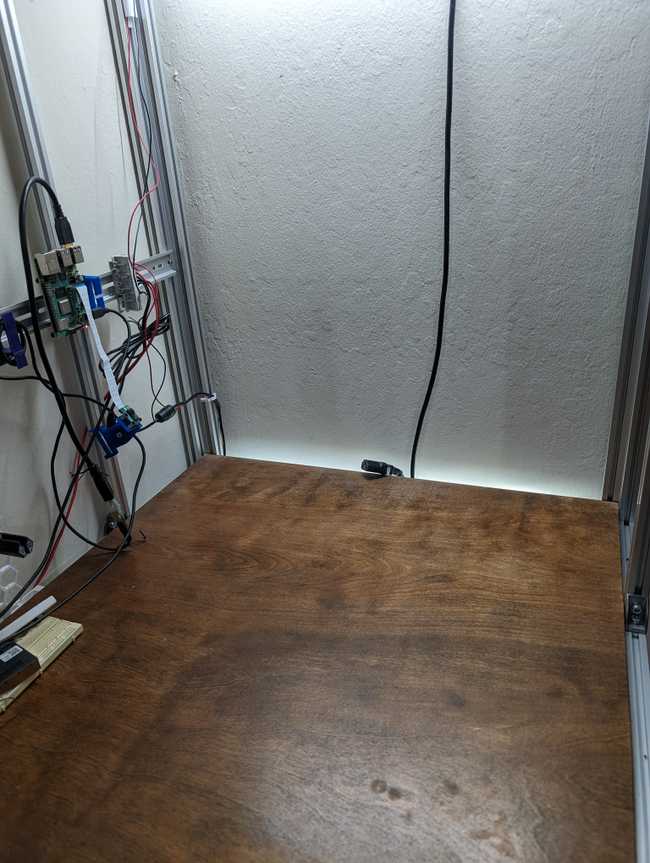
In order to flip the printer upside down to install the new Y rails, I took it downstairs to the living room to have more room to work with. I then decided that I should probably print out a bunch of wiring organizers before I put it back so I don’t need to pull it out a few more times.


