I'm doing AdaFruit's light painting tutorial... but I haven't a CLUE.

Details

AdaFruit has done a series of light painting tutorials.

First, they did a tutorial with the NeoPixel strips and an Arduino. Then they upgraded it to the DotStar LEDs and used a Raspberry Pi. Then they downgraded the LEDs to the NeoPixels and switched to CircuitPython. And most recently, they did it with a CLUE and the DotStar LEDs.

Coincidentally, just days before they posted their most recent tutorial, I had gotten motivated to try doing something along the same lines, except instead of using a CLUE, I figured I’d get the Feather M4 Express.

Thus, I’m doing AdaFruit’s light painting tutorial… but I haven’t a CLUE.

This is my completed half-successful effort to make a usable lightpainting staff with the Feather M4 Express, a OLED feather, and 60 pixels in an Aluminum channel.

Parts List

QtyPart #DescriptionManufacturer
12900Adafruit FeatherWing OLED - 128x32 OLED Add-on For FeatherAdafruit
13857Adafruit Feather M4 ExpressAdafruit
12830Stacking Headers for FeatherAdafruit
1LED strip1M 60 LEDs/m IP30 SK9822 stripBTF-Lighting
1B5390ANODAUniversal LED strip channelSuperBrightLEDs
1CAB-145764-pin JST SM Plug + Receptacle Cable SetSparkfun
110oz jarMoldable thermoplasticsPollyPlastics
3OSTTA024163Screw terminalsOn Shore Technology Inc.
1UPS1E102MHD1TO1000 uF radial electrolyticNichicon
17cm x 9cm PCBGeneric 7cm x 9cm PCB.Generic
1EGS10C-20GElectronics grade silicone adhesiveChipQuik

Build Log

Step 5: In which I get software working but run out of RAM

Goal: Get a working CircuitPython light staff

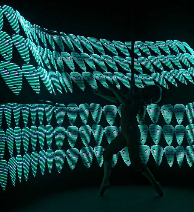
An image from the inaugural photo shoot with the light staff:

Pic

I’d mostly ignored the CircuitPython implementation of this for a while, in favor of the ATMega328 version.

My ATMega328 version does a wide variety of interesting effects and 144 pixels is close to the limit of the amount of RAM in the device. After I spent a weekend trying out the different FastLED patterns and figuring out which ones I like, it’s been actually really smooth sailing.

When I try to find the same functionality on the CircuitPython side, it’s not really there. The thing I keep coming back to is that FastLED is really two libraries: One library is the low-level code that talks to the LEDs. The second library is the incredibly useful math-related code that makes it friendly to code interesting LED patterns.

There’s an extremely large category of useful things that can be done with procedural texturing. A long time ago, I was studying movie effects and they covered how to do procedural textures and I found that you can go really far with them.

So for a while, it was sitting near-abandoned while I worked on other things because I was perfectly able to do just about all I wanted to do on a device that has several orders of magnitude less capability than an M4.

I did finally hit on the real thing that was worth investigating, however: Loading bitmaps from the virtual disk and tiling them.

I got a reasonable version of things going with a 60 LED strip where I would load a bitmap into memory and pan through it or tile it, and that actually feels pretty reasonable.

Except that once I moved from 60 LEDs to a 144 LED strip and I replaced the 60 LED bitmap files with bigger files, I started running out of RAM. Even relatively tiny 40k bitmap files were causing problems.

I have some long term reservations. CircuitPython has not really felt any easier to deal with for me than an Arduino for the task of making a light painting staff, even though I’d started out thinking that it was the Arduino side of things that was slowing me down when it was really that I needed to study FastLED a little bit harder. In fact, other than the easy bitmap work, it’s been harder.

I could refactor more code to work a little more like the code in the CLUE demo looks to work and pull rows off of the SD card which would enable me to avoid running out of RAM, but that’s going to make my code a lot more complicated and that doesn’t get me anywhere. Again, if I’m going to make the code more complicated, it’s just as easy for me to work in the Arduino environment.

Given that there aren’t really any Feather boards with significantly more RAM, I decided that the upgrade path was to get a Teensy 4.1. A Teensy 4.1 has an NXP iMXRT1062 processor and it’s got a megabyte of RAM, so even with my inefficient workflow, it’s plenty.

So, I’m going to categorize this as a half-failure because it’s a completely working board for driving a 60 pixel LED staff with bitmaps but I couldn’t get it to scale further.

A year or two from now, this is going to be solidly practical and this particular project isn’t really a reason for you to not try CircuitPython. There are noises that there will be a Feather with a similar processor to the Teensy 4.1 and, if there’s not, there’s almost certainly going to be something else with more memory and CPU than the current crop because progress marches on.

Step 4: Actually building out some hardware

Goal: Get a lightpainting staff that I can hold

There’s a perfectly good tutorial on the Adafruit site about how they want to build a light painting stick, but I don’t feel like it necessarily represents my needs. I tend to want to wiggle my strips side-to-side and so I tend to want to grab it at different distances up and down the strip.

Also, I’m not at all ready to commit to having one single universal controller, so I’m just keeping the strip and everything else separate for the time being.

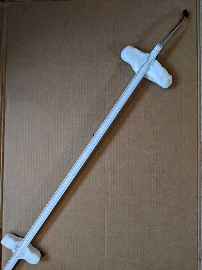
The advent of LED strip lighting everywhere means that you can just get a perfectly reasonable aluminum extrusion to hold a LED strip that comes with a built-in diffuser, so I just got one of those.

I spent a bit of time trying to make a good hand-grip in CAD but then it occurred to me that I could just get the low-temperature thermoplastic materials that cosplayers use and just sculpt my handles by hand, the brand name that everybody knows is “Worbla” but there’s actually a zillion brands out there.

So, the materials list for building my staff, which is useful for both my CircuitPython version as well as my ATMega328 version, is something like this:

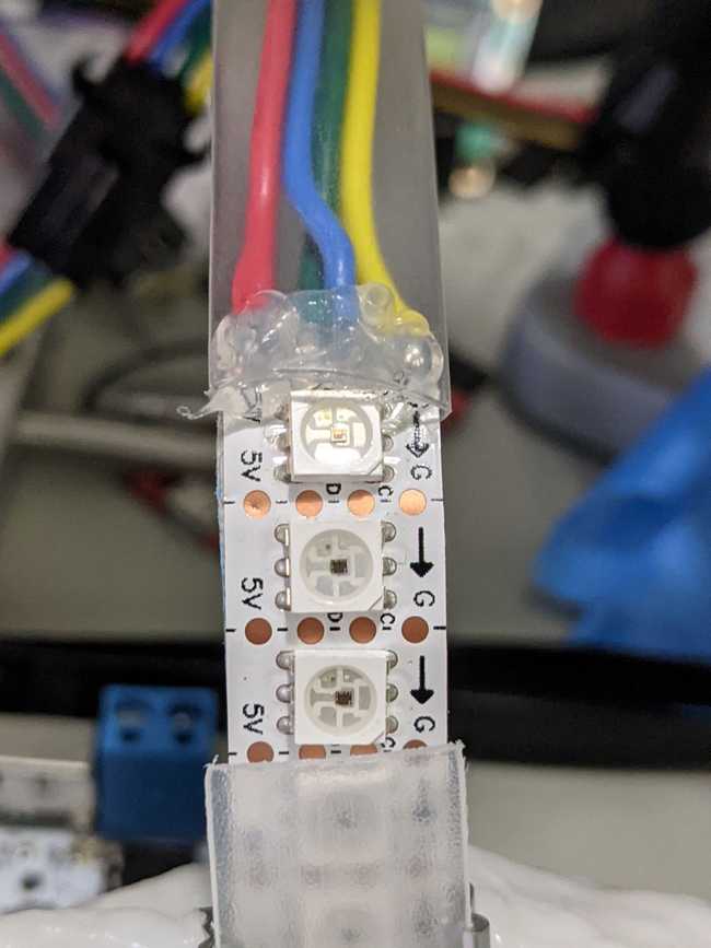
  • A strip of APA102/SK9822 “DotStar” pixels
  • A metal LED mount extrusion (I used the TAMI LED Strip Channel from SuperBrightLEDs)
  • 4 Pin JST-SM connectors
  • Heat shrink tubing
  • Low temperature thermoplastics (I used Polly Plastics brand)
  • Electronics grade silicone

While I was doing this, I also took a generic 7x9cm PCB and soldered down a set of screw-terminal connectors and a 1000 uF bulk capacitor:

Board

The whole appeal to the thermoplastics is that it’s kind of like a clay-sculpting experience and I’ve already got a heat-gun. And if you smoosh it up against the strip while the plastic is still hot, it’ll just stick like glue. I made the first strip with a single handle at the top that wraps around the back and that worked really well most of the time, but I realized that it really helps to add a second handle at around the mid-point, so my current staff has both, so here’s what my staff looks like:

Board

I’m still fighting a bit with the connectors. I had started out with some random connectors I picked up off of Amazon, but they were clearly flimsy and the first two outings with my strip had me fighting with things.

I decided to get the JST-SM pigtail connectors that SparkFun sells because they are very obviously thicker gauge wire and this time I’ve glued them down with electronics grade silicone to the board and then I put that in heat shrink tubing:

Board

Step 3: In which I actually look through the example source bundle and refactor

Goal: Get more code working.

I’ve been working on two different approaches to this problem, in parallel. On one side, there’s the Feather M4 running CircuitPython. On the other, there’s a ATmega328 running Arduino C++.

In both cases, I’ve got buttons and the driver for an APA102 “DotStar” strand. It’s just that on the Feather M4, I’ve got an OLED display as well.

Last weekend I made some huge progress on the ATMega328 version, which is largely because a lot of people have spent a lot of time since before CircuitPython was a thing doing collective effort on the FastLED library. Therefore, there are both tools and examples out there for a lot of useful things to use as inspiration, but only with FastLED.

I also question if emulating it blindly is the right thing, because there’s a lot in FastLED that works really well to get a lot of moderate-complexity math done with 8 and 16 bit integers and when you look at how an M4 has a FPU and the M7 cores have absurd amounts of processing power, it’s probably better for CircuitPython to avoid making you think about those sorts of issues.

Given this, I decided is that I really should use the M4 where it’s stronger: It’s got a lot more storage for bitmap patterns. So, all of this is going to be more bitmap-oriented.

Also, I discovered that I can totally violate a lot of rules of good sense and turn the power on my strip down to 10%, I don’t need to worry too heavily about the power consumption and there seems to be ampre power from my USB port.

I actually poked through the source bundle for the tutorial and there’s some neat stuff there. For example, there’s a RichButton library that frankly ought to become part of the standard library bundle because it does about the same thing as an incredibly useful library on the Arduino side that I tend to lean on.

I also looked at how they were laying out things and did a big refactor to my codebase.

I decided I don’t necessarily need a virtual filesystem with the ability to drag images on and use them for painting nearly as much as I need the ability to have a set of patterns loaded and ready to cycle through, so I’m writing my converter on the desktop side, which means I can use regular Python and so my converter looks like this:

from PIL import Image

img = Image.open("rainbow.bmp")

baseheight = 9
wpercent = (baseheight/float(img.size[1]))
vsize = int((float(img.size[0])*float(wpercent)))
img = img.resize((vsize,baseheight), Image.ANTIALIAS)
print (list(img.getdata()))
print (vsize)

And the code, after refactoring, looks more like this:

# Write your code here :-)
import board
import digitalio
import displayio
import time
from digitalio import DigitalInOut, Direction
from neopixel_write import neopixel_write
import adafruit_dotstar
import terminalio
from adafruit_display_text import label
from richbutton import RichButton
import adafruit_displayio_ssd1306
from adafruit_debouncer import Debouncer

NUM_PIXELS = 60
PIXEL_PINS = board.SCK, board.MOSI # Data, clock pins for DotStars
PIXEL_ORDER = 'bgr'               # Pixel color order
GAMMA = 2.4                   # Correction for perceptually linear brightness
BRIGHTNESS = 0.1
DELAY = 0.1

displayio.release_displays()

i2c = board.I2C()
display_bus = displayio.I2CDisplay(i2c, device_address=0x3C)
display = adafruit_displayio_ssd1306.SSD1306(display_bus, width=128, height=32)

bitmap = [(253, 29, 13), (254, 0, 140), (209, 3, 255), (58, 3, 254), (0, 81, 254), (255, 191, 0), (255, 43, 6), (255, 0, 132), (213, 2, 254), (73, 0, 255), (148, 255, 0), (253, 215, 1), (254, 55, 0), (255, 0, 113), (232, 3, 247), (5, 251, 24), (123, 255, 0), (251, 226, 3), (255, 69, 0), (255, 0, 88), (1, 255, 182), (0, 252, 39), (107, 255, 0), (244, 234, 3), (255, 93, 0), (0, 168, 255), (2, 255, 202), (0, 252, 48), (92, 255, 0), (232, 245, 4), (18, 11, 252), (0, 144, 255), (3, 255, 215), (0, 254, 61), (70, 255, 0), (173, 0, 255), (36, 3, 253), (0, 125, 255), (2, 248, 224), (0, 255, 87), (255, 2, 178), (189, 0, 253), (39, 0, 252), (0, 117, 255), (3, 241, 235)]
bitmap_height = 9

# pylint: disable=too-many-instance-attributes
class M4LightPainter:

    # pylint: disable=too-many-arguments
    def __init__(self, num_pixels, pixel_order, pixel_pins, gamma, brightness, delay):

        self.mute = True
        self.program = 0
        self.num_pixels = num_pixels
        self.delay = delay

        # Turn off onboard NeoPixel
        onboard_pixel_pin = DigitalInOut(board.NEOPIXEL)
        onboard_pixel_pin.direction = Direction.OUTPUT
        neopixel_write(onboard_pixel_pin, bytearray(3))

        # Configure the DotStar pixel bus
        self.pixels = adafruit_dotstar.DotStar(PIXEL_PINS[0], PIXEL_PINS[1], NUM_PIXELS, brightness=brightness, auto_write=False)

        # Turn off the onboard red LED
        self.red_led = digitalio.DigitalInOut(board.D13)
        self.red_led.direction = digitalio.Direction.OUTPUT
        self.red_led.value = False

        # Configure the buttons
        self.button_a = RichButton(board.D9)
         
        self.button_b = RichButton(board.D6)

        self.button_c = RichButton(board.D5)

    def fill_color(self, color):
        for i in range(self.num_pixels):
            self.pixels[i] = color

    def clear_strip(self):
        self.fill_color((0,0,0))

    def show_screen(self):
        # Make the display context
        splash = displayio.Group(max_size=10)
        display.show(splash)

        if self.mute:
            text = "Program: {0}".format(self.program)
            text_area = label.Label(terminalio.FONT, text=text, color=0xFFFF00, x=0, y=10)
            splash.append(text_area)

    def setup_program(self):
        self.show_screen()

    def run(self):
        print("Hello, CircuitPython!")
        self.show_screen()

        self.clear_strip()
        self.pixels.show()
        action_list = [None, None, None]

        count = 0

        while True:
            if self.mute:
                self.clear_strip()
                self.pixels.show()
            else:
                count = count + 1
                count = count % 5

                for i in range(self.num_pixels):
                    self.pixels[i] = bitmap[count * bitmap_height + (i % bitmap_height)]
                self.pixels.show()
                time.sleep(0.1)


            action_list[0] = self.button_a.action()
            action_list[1] = self.button_b.action()
            action_list[2] = self.button_c.action()
            if action_list[0] is RichButton.TAP:
                print('Mute Toggle - {0} {1}'.format(self.mute, self.program))
                self.mute = not self.mute
                self.setup_program()

            if action_list[1] is RichButton.TAP:
                print('Program + - {0} {1}'.format(self.mute, self.program))
                self.program = self.program + 1
                self.program = self.program % 8
                self.setup_program()

            if action_list[2] is RichButton.TAP:
                print('Program - {0} {1}'.format(self.mute, self.program))
                self.program = self.program - 1
                if self.program < 0:
                    self.program = 7
                self.setup_program()


M4LightPainter(NUM_PIXELS, PIXEL_ORDER, PIXEL_PINS, GAMMA,
                 BRIGHTNESS, DELAY).run()
Step 2: Buttons, buttons who's got the button

Goal: Get a skeleton of a program going that demonstrates the basic code flow.

So, when I’m talking about documentation, here’s one example of what I ran up against. The OLED FeatherWing tells you how to use the buttons in the Arduino world, but not in the CircuitPython world, which meant that I had to do some digging because the only tutorial I found with a quick google search was for a different device and didn’t at all apply to my wing.

It looks something like this:

import board
import digitalio

button_a = digitalio.DigitalInOut(board.D9)
button_a.direction = digitalio.Direction.INPUT
button_a.pull = digitalio.Pull.UP

while True:
    if not button_a.value:
        print("fffff")

And then, what I really wanted is:

import board
import digitalio
from adafruit_debouncer import Debouncer

raw_button_a = digitalio.DigitalInOut(board.D9)
raw_button_a.direction = digitalio.Direction.INPUT
raw_button_a.pull = digitalio.Pull.UP
button_a = Debouncer(raw_button_a)

while True:
    button_a.update()
    if button_a.fell:
        print('Just pressed')
    if button_a.rose:
        print('Just released')
    if button_a.value:
        print('not pressed')
    else:
        print('pressed')

Because then you get a debouncer library that’s really a fundamental requirement for doing any sort of real input from a button.

Now, the idea here is that I’m going to use the OLED display to tell me which program I’m in when the light-show is “muted”, but when the light-show is going on, I want the OLED to be off so it doesn’t disturb my painting.

So, my completed user-interface code looks something like this:

import board
import digitalio
import displayio
import time
import neopixel
import adafruit_dotstar
import terminalio
from adafruit_display_text import label
import adafruit_displayio_ssd1306
from adafruit_debouncer import Debouncer

program = 0
mute = True

num_pixels = 3
pixels = adafruit_dotstar.DotStar(board.SCK, board.MOSI, num_pixels, brightness=0.1, auto_write=False)

displayio.release_displays()

red_led = digitalio.DigitalInOut(board.D13)
red_led.direction = digitalio.Direction.OUTPUT

board_led = neopixel.NeoPixel(board.NEOPIXEL, 1)

i2c = board.I2C()
display_bus = displayio.I2CDisplay(i2c, device_address=0x3C)
display = adafruit_displayio_ssd1306.SSD1306(display_bus, width=128, height=32)

def show_screen():
	# Make the display context
	splash = displayio.Group(max_size=10)
	display.show(splash)

	if mute:
		text = "Program: {0}".format(program)
		text_area = label.Label(terminalio.FONT, text=text, color=0xFFFF00, x=0, y=10)
		splash.append(text_area)

def setup_oled_buttons():
	raw_button_a = digitalio.DigitalInOut(board.D9)
	raw_button_a.direction = digitalio.Direction.INPUT
	raw_button_a.pull = digitalio.Pull.UP
	button_a = Debouncer(raw_button_a)
	 
	raw_button_b = digitalio.DigitalInOut(board.D6)
	raw_button_b.direction = digitalio.Direction.INPUT
	raw_button_b.pull = digitalio.Pull.UP
	button_b = Debouncer(raw_button_b)
	 
	raw_button_c = digitalio.DigitalInOut(board.D5)
	raw_button_c.direction = digitalio.Direction.INPUT
	raw_button_c.pull = digitalio.Pull.UP
	button_c = Debouncer(raw_button_c)

	return (button_a, button_b, button_c);

def setup_program():
	show_screen()

button_a, button_b, button_c = setup_oled_buttons()

print("Hello, CircuitPython!")
show_screen()

red_led.value = False
board_led[0] = (0,0,0)
pixels[0] = (0,0,0)
pixels[1] = (0,0,0)
pixels[2] = (0,0,0)
pixels.show()

while True:
    if mute:
    	pixels[0] = (0,0,0)
    	pixels[1] = (0,0,0)
    	pixels[2] = (0,0,0)
    	pixels.show()
    else:
	    pixels[0] = (0,255,255)
	    pixels[1] = (0,255,0)
	    pixels[2] = (255,255,0)
	    pixels.show()

    button_a.update()
    button_b.update()
    button_c.update()
    if button_a.fell:
        print('Mute Toggle - {0} {1}'.format(mute, program))
        mute = not mute
        setup_program()

    if button_b.fell:
        print('Program + - {0} {1}'.format(mute, program))
        program = program + 1
        program = program % 8
        setup_program()

    if button_c.fell:
        print('Program - {0} {1}'.format(mute, program))
        program = program - 1
       	if program < 0:
       		program = 7
       	setup_program()

Advantages of CircuitPython over Arduino so far:

  • Improved develop-test cycle time.
  • Better feedback.

Disadvantages of CircuitPython over Arduino:

  • I keep running into issues with the reference-style docs. It’s probably worse given that I’ve worked as a professional programmer doing Python.

Step 1: Acquire parts and get loosely working

Goal: Determine if all of the bits are going to fit together as I’d hoped.

The goal was to use CircuitPython. Just because I can program things in assembler (Or C++) doesn’t mean I should do it often. At the same time, I didn’t want to use a whole Raspberry Pi on it, because there’s too many ways that can go weird.

So I figured the desired configuration was a M4 Feather Express (because CircuitPython is going to require a lot more CPU and RAM and Storage than doing it in C++) and an OLED FeatherWing so I’d have something with buttons and a little display for debugging.

I did some pondering and adjusting and pulled the trigger on a DigiKey order on Tuesday, with an expected delivery date of Saturday.

They were out of the Adafruit packaged stacking headers, so I got some general-purpose 12 pin stacking headers and 16 pin stacking headers, which actually cost me more than just getting the Adafruit branded bundled product.

On Wednesday, AdaFruit posted an article about building it with a CLUE. I guess this provides me with a realism check that it’s totally a thing I could do, but at the same time, the CLUE is the least useful form factor for my needs (even as it’s totally an excellent form factor for a lot of other folks) so I’m diverging from their design on at least one hardware point regardless.

It was supposed to arrive on Saturday, but it turns out it showed up Thursday afternoon.

This is great, because I was taking a company-approved mental health day because Coronavirus on Friday.

Now, past me had done present me a solid. I had a bunch of random electronic bits that I’d sent off to DirtyPCBs. Pretty much, the goal was to fill a 5cm × 5cm space. In there was a tiny breakout that holds three APA102 LEDs in a string, so I soldered one up while I was putting the stacking headers on.

I wrote up a quick hello world sort of app to demonstrate that everything actually worked.

The big downside is that if you don’t have a LiIon battery connected, the charger circuit blinks the yellow charging light and that’s just plain not nice for a lightpainting.

Observations on CircuitPython, so far:

  • I tried using Mu. It’s OK. It’s probably great for the actual target audience, same as the Arduino GUI target audience. However, after it somehow doesn’t want to work in serial port mode, I switched to using my usual Sublime and using PuTTY to connect to the serial port.
  • The documentation is heavily weighted towards task-based intros and away from reference materials. This is weird, different, and strange for me. Again, this is probably actually perfect for the target audience and I have a huge amount of respect for the AdaFruit documentation team. It’s just that it doesn’t work the way I necessarily want.
  • The USB bootloader is really quite nice. I can just edit a Python source file as if it’s a keydrive attached to my computer. Device programmers are annoying. Can we have more embedded things that work like this?
  • The library support is fine for now. Basically, what you end up doing is… grabbing a tarball of all of the contrib libraries and dropping it into a folder. Eventually this is going to require them to make some sort of virtualenv sort of library manager, but I’d rather see this done right than punted.

Posted:

Updated: